Only a few measurement technology manufacturers can keep up with the rapid development of electromobility and the high measurement requirements for electric motors

The history of the ever-changing automotive technology began almost 140 years ago. Step by step, development led to ever more efficient and powerful combustion engines. However, due to the abrupt demand to switch to electromobility, progress must now take place in leaps rather than small steps - this rapid pace means that developers are often on the edge of their own experience. With the high demands of e-mobility, only a few measurement technology manufacturers can keep up. At the forefront of development is Labortechnik Tasler GmbH.
To determine the efficiency of an electric motor, you have to put the mechanical power output in relation to the electrical power input. Both measured variables have their own pitfalls.
Fortunately, it is possible to reduce the problem to electrical measured quantities, since the long history of combustion engines has already provided a great deal of experience and also suitable measurement technology for mechanical power measurement.
What about electrical power measurement? First of all, it is generally true that it is difficult to measure electrical power consumption directly. In addition, according to the standard specifications of DIN IEC 60034-2-3, a high measurement accuracy is required:
"The nominal accuracy of power meters must be 0.3% or better, based on the apparent power at the rating point of the motor under test. This applies to the total uncertainty of power measuring equipment including possible transducers."
Point 7.2 of this standard (“Additional losses due to the voltage drop in the frequency converter”) defines further tightening, so that you actually have to be better than 0.3%.
So we have two measured quantities (current and voltage) whose errors add up according to the error propagation law in the multiplicative calculation of the power (U*I).
Both quantities individually (current and voltage considered separately) are a concatenation of at least four errors:
The sum of these errors determines the resolution of the two measured quantities (voltage and current).
Since all 4 errors of both measured quantities add up according to the error propagation law, we have a total of 8 error sources, the sum of which must not exceed 0.3%. As mentioned above (reference to the standard, point 7.2), one should even be a bit better.
So, on average, each error source may contribute only roughly 0.03% error. That is really sporty!
This means that a square wave signal must be detected cleanly on 53 harmonics and a triangle signal on 9 harmonics.
At the same time, the amplitude error must not be greater than 0.03% over this frequency band and the synchronicity must be better than 3ns.
Because of these high synchronism requirements and because of the need to be able to multiply U(t) and I(t) with each sample without additional phase errors, both measured quantities (U and I) must be acquired at the same sampling rate. However, when operating an electric motor, the frequency and amplitude of the sinusoidal supply signal must also match: small speed corresponds to a small amplitude. Large speed corresponds to a large amplitude.
So if you want to cover a speed range from 1% to 100% of the motor, even the amplitude in the slow speed range is only 1% of the amplitude at full speed.
Thus, the full scale value must not only be resolved to 1/0.03% = 3333 steps, but to 333333. This corresponds to an effective resolution of an AD converter of 18.3 bits. And this after subtracting all noise and distortion of this AD converter.
This brings us to the core of this article: If you don't have at least a 20-bit AD converter, or better a 24-bit AD converter with at least 1MHz (better 2MHz or 4MHz) sampling rate, you don't even need to start measuring the power of a PWM driven electric motor.
At the same time, the synchronicity over all measurement channels must be better than 3ns (better 1ns)!
Furthermore, high signal voltages come into play, which, in addition to a considerable safety risk, also place extreme demands on the input capacities of the measurement technology.
Imagine a 400V battery driven E-motor, which pulls up the voltage from 0V to 400V with 10kHz pulse rate (and pulls down to 0V immediately afterwards). If you have only 10pF of stray capacitance in the signal path, then those 10pF must be charged or discharged by 400V 20000 times per second.
In the most leisurely case, the capacitor is just fully charged when it is discharged again. Then at 50% pulse width you have exactly 50µs time to charge the capacitor.
In reality the edges are much steeper. The capacitor will be fully charged in about 500ns. Then the charge current of this assumed stray capacitance is already 8mA.
Harmless?
No, unfortunately not! For slow speeds, the rule of thumb for the maximum measurement error was given above: "Measuring range / 333333".
The 8mA error charging current corresponds to a just tolerable error if the measuring current would be in the order of 2.7kA (or greater).
In short: the allowed stray capacitance of the measuring channels must be extremely low!
And coupled with the necessary protection against high voltage and the absolute necessity to completely exclude current loops (because these would suffer sensitive interference from the magnetic field of the E-motor), the channels must absolutely be galvanically isolated from each other and at the same time have an extremely low stray capacitance with respect to the housing.
If only one of these requirements (sampling rate, resolution, synchronicity, galvanic isolation with low stray capacitance) is not perfectly implemented, the efficiency measurement according to standard DIN IEC 60034-2-3 will fail.
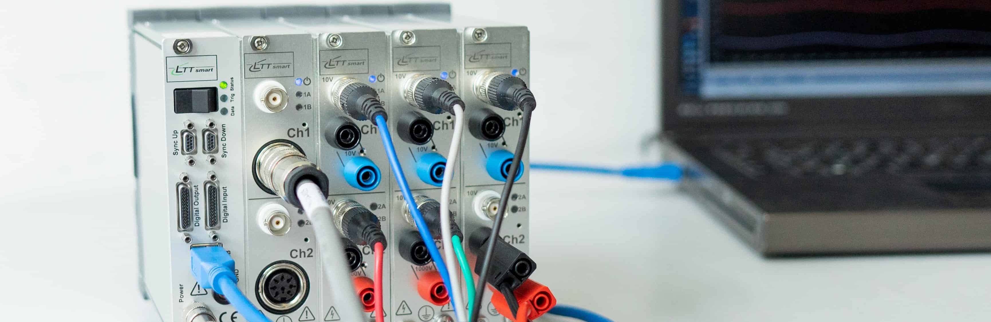
All these points have been carefully coordinated and implemented in the LTTsmart measurement system from Labortechnik Tasler GmbH. The measurement technology specialist has been established on the market for more than 25 years and was already active in high-resolution megahertz ranges when the measurement technology market slowly switched from DOS to Windows.
The demands of e-mobility are now driving the market into this niche from two directions: slow PC measurement technology is now far from sufficient in points bandwidth. And fast oscilloscopes are nowhere near reaching the required details with the resolution.
But efficiency determination needs the connection between two signal worlds:
The (fast) electrical and the (slow) mechanical power measurement.
The latter can of course also be covered highly synchronously by the LTTsmart.
In many cases, however, it makes sense to acquire the many (slow) additional pieces of information, such as temperatures, by means of additional measuring devices from Gantner Instruments, which work seamlessly with the LTTsmart.
The user benefits from the fact that the LTTsmart is perfectly matched to the demanding measurement task and works smoothly with other measuring instruments.
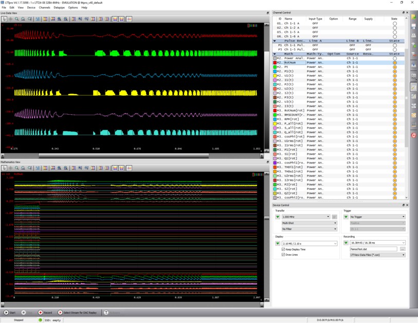
The comprehensive functionality of the power analyzer is available in both the cross-industry software solution LTTpro and in the Gantner GI.bench and connects the two worlds highly synchronously. Slow, medium-fast and very fast measurement signals are combined online to produce the required analysis variables.
The large amounts of data required for the calculation of the electrical performance indicators indicated above remain unnoticed by the user in the background. At the same time, however, the user or a decision criterion that can be set via software can record entire sections of this fast raw data and analyze them at any time in order to be able to discuss any anomalies in the logged characteristic values.
Whether for research purposes or for process and quality monitoring: as a user, you always have full access to all signal worlds. From the overview to the finest detail.
This makes the Power Analyzer solution (among many other measurement solutions) from LTT the perfect - and even unique - total package, thanks to which you can also keep up with the rapid development of electromobility.