Each axle counts:
EMC measurements for safe operation on track switching devices

To ensure safe rail operations at all times, it must be ensured, among other things, that there is only ever one train or rail vehicle on a given section of track. For this purpose, the track network is divided into so-called block sections, which are secured by corresponding entry and exit signals. Electronic track switching devices, i.e. axle counters and wheel sensors, are used for the automated detection of the passage of rail vehicles. Only when as many axles or wheels have left a block section as have previously entered it is the track section reopened for following or oncoming vehicles.
In Germany, inductive rail contacts are mostly used for this purpose. These consist of a transmitter on the outside of the rail and a receiver on the inside of the rail. When a wheel moves through the alternating magnetic field, this results in a field change. The axle is counted. Each counting point includes two systems mounted in pairs with some distance between them to detect the direction of travel. The direction of travel can be derived from the time shift of the field direction change to the second transmitter/receiver pair.
To avoid miscounting and any associated service interruptions, investigations into the electromagnetic compatibility (EMC) of the sensors are necessary. In addition, all rail vehicles must also be tested to ensure that they do not generate any electromagnetic interference outside the permitted limits in the area of the axle counters. For this purpose, Siemens has, among other things, a corresponding measuring point at its Test and Validation Center (PCW) in Wegberg, near the Dutch border, to verify the compatibility of rail vehicles with track switching equipment. The measuring point is located on a straight section of the 4.8 km long test oval (see Pic. 1).
For the measurement of the highly dynamic and inhomogeneous electromagnetic fields during the passage of a train, air coil sensors, each for the x-, y- and z-direction, are attached to the sides of the rails. To detect possible asymmetries, the left and right sides of the vehicle must be tested. This means that 6 measurement channels must be synchronously recorded and evaluated for each measurement point. Due to the large number of different types of axle counters and wheel sensors, the measuring system must cover a very wide operating frequency range from a few kHz to over 1 MHz.
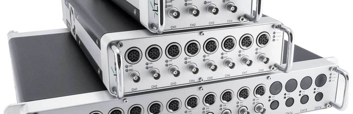
For many years, Siemens in Erlangen and Wegberg has relied on the LTT24 measuring devices from Labortechnik Tasler. The LTT24 can acquire up to 16 measuring channels with a sampling rate of up to 4 MHz per channel. The high resolution of 24 bits has proven to be a particular advantage: This makes it possible to cover the entire working frequency range with just a single measurement. Previously, this required two measurements or twice as many measurement channels, each for the kHz and MHz ranges. Moreover, the high synchronism of the sampling of the individual channels is crucial for an accurate evaluation.
The LTT24 also enables Siemens engineers to operate mobile EMC measuring stations at any point in the rail network and without installed track switching equipment - e.g. when unknown vehicles of foreign railroad companies enter the border. The measuring devices from Würzburg are now also in use at Alstom as well as at the Indian TATA. The complete mathematical analysis of the measurement data (incl. FFT etc.) in accordance with the relevant standards and guidelines was implemented at Tasler on behalf of the customer in the LTTpro software supplied.
Do you have any questions? We will be happy to answer. Write us a message or simply give us a call:
Contact us